motors
Images for the Motors clinic. These may be deprecated as content has been moved into the Motors website. — 12 images
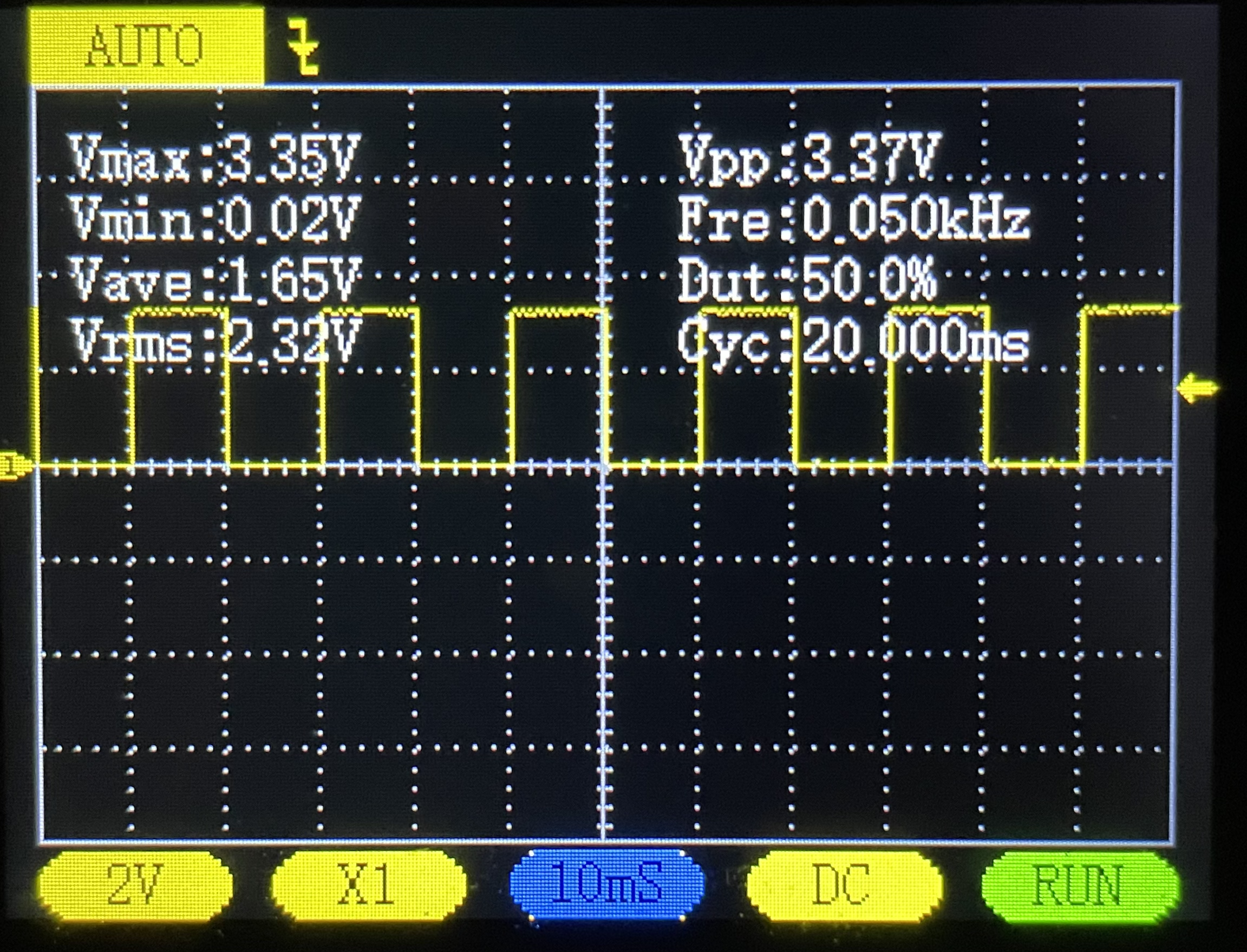
An oscilloscope display showing an electrical waveform measurement with voltage and frequency data. The screen displays a yellow square wave pattern with measurements including Vmax (3.35V), Vmin (0.02V), Vave (1.65V), Vrms (2.32V), Vpp (3.37V), frequency (0.050kHz), duty cycle (50.0%), and cycle time (20.000ms). This is a screenshot of oscilloscope software or hardware used for electronics analysis and measurement.
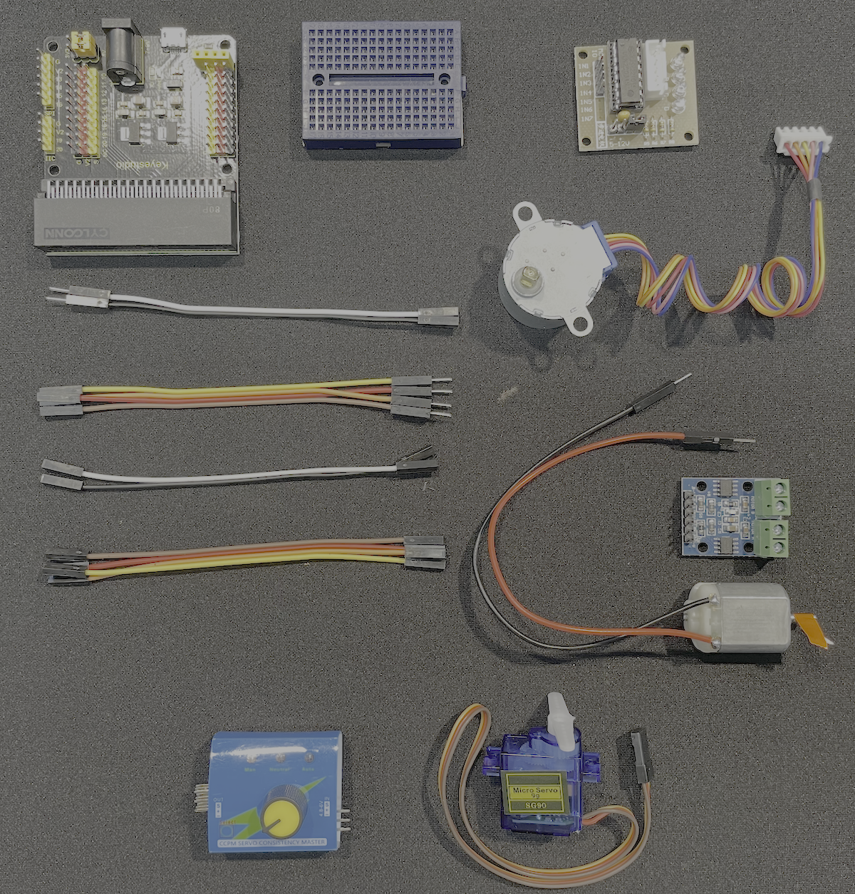
A flat-lay product photograph showing various electronic components and hardware used in robotics or maker projects, including circuit boards, motors, servos, wiring harnesses, and control modules arranged neatly on a gray surface. This appears to be a kit or collection of parts for building motorized projects, typical of what The League of Amazing Programmers would use in their youth coding and robotics curriculum.

A flat-lay product photo of various electronic components and hardware used for robotics and motor control projects, arranged neatly on a gray background. The collection includes servo motors, a microcontroller board, circuit boards, jumper wires, connectors, and other electrical components. This appears to be a kit or collection of parts for The League's motors clinic curriculum.

A photograph of a Keyestudio circuit board module with a Cytronix 80P connector at the top. The black PCB board features various electronic components including resistors, capacitors, and connector pins arranged in rows (numbered 0-7 on the sides) with red and yellow terminal blocks. This appears to be a motor control or expansion board commonly used in educational robotics projects.
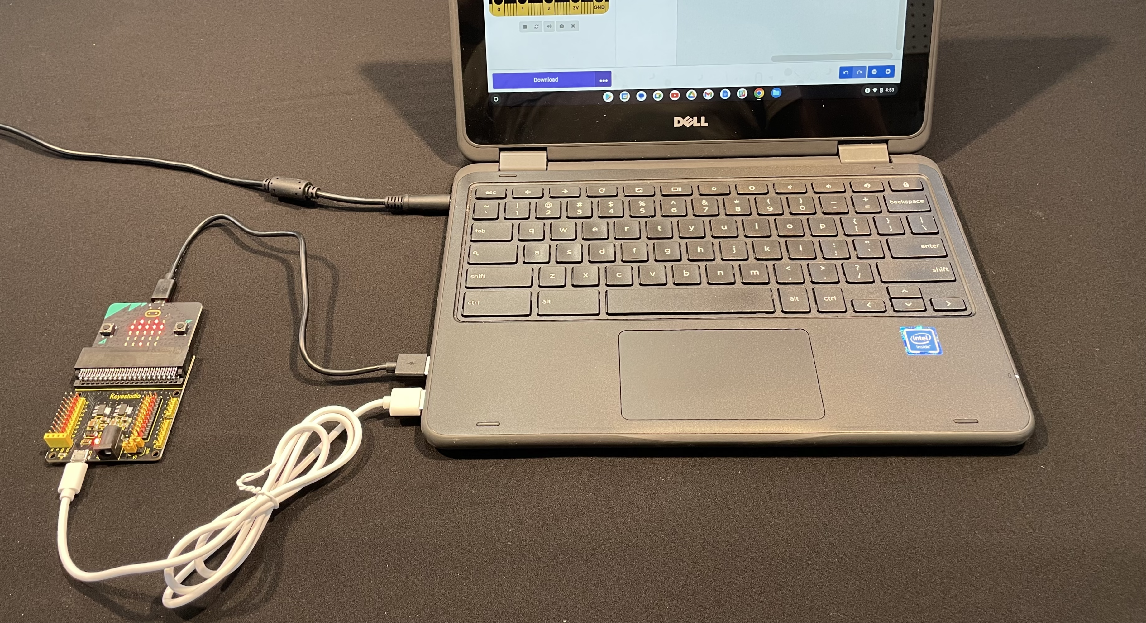
A Dell laptop is connected via USB cable to a microcontroller board (appears to be a micro:bit or similar educational circuit board) with an LED grid visible on top and colorful component headers below. The laptop screen displays what appears to be a programming interface or application. This setup demonstrates a typical hardware-software integration used in youth coding education.

A close-up photograph of an electronic circuit board with green terminal blocks at the top, various resistors, capacitors, and integrated circuits on a blue PCB base, and connector pins at the bottom. This appears to be a motor control or driver module used in robotics projects.
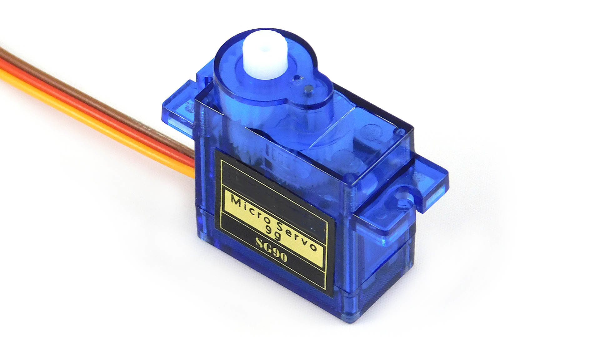
A blue microservo motor (labeled SG90) photographed against a white background with colored wires (red, yellow, brown) attached. This is a common small servo motor used in robotics and electronics projects, typical of components used in youth coding and hardware education.
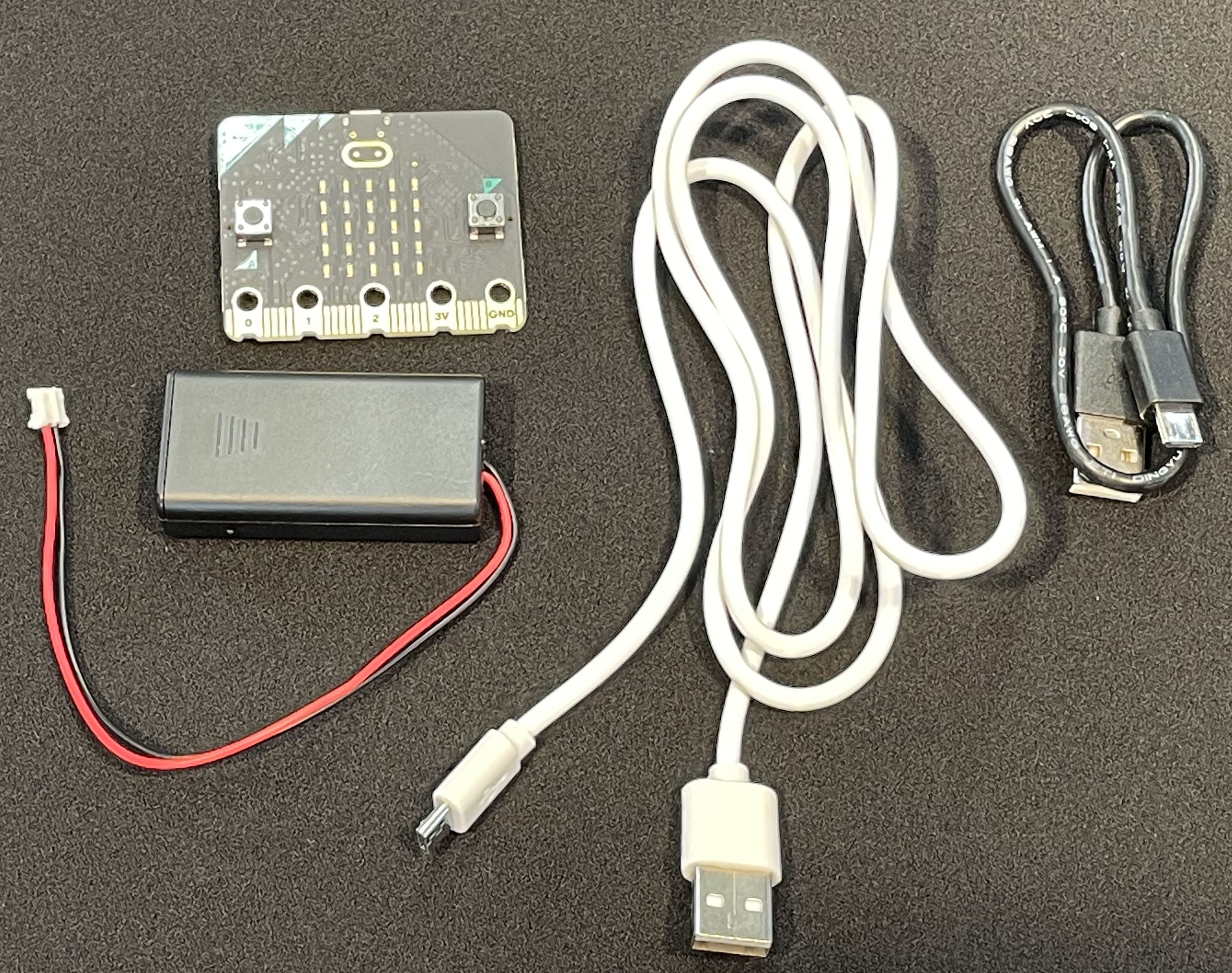
A flat-lay product photo of microcontroller hardware components arranged on a dark surface. The image shows a micro:bit board (top left), a battery pack with red and white wires (left), white USB cables, and a black USB cable connector (right). These are typical components used in educational coding and robotics projects.

A Dell laptop is connected to a microcontroller board (appears to be a micro:bit or similar educational circuit board) with USB cables. The board features colorful components including an LED matrix display and is positioned on a dark surface next to the laptop. The laptop screen displays what appears to be a programming interface or application window.
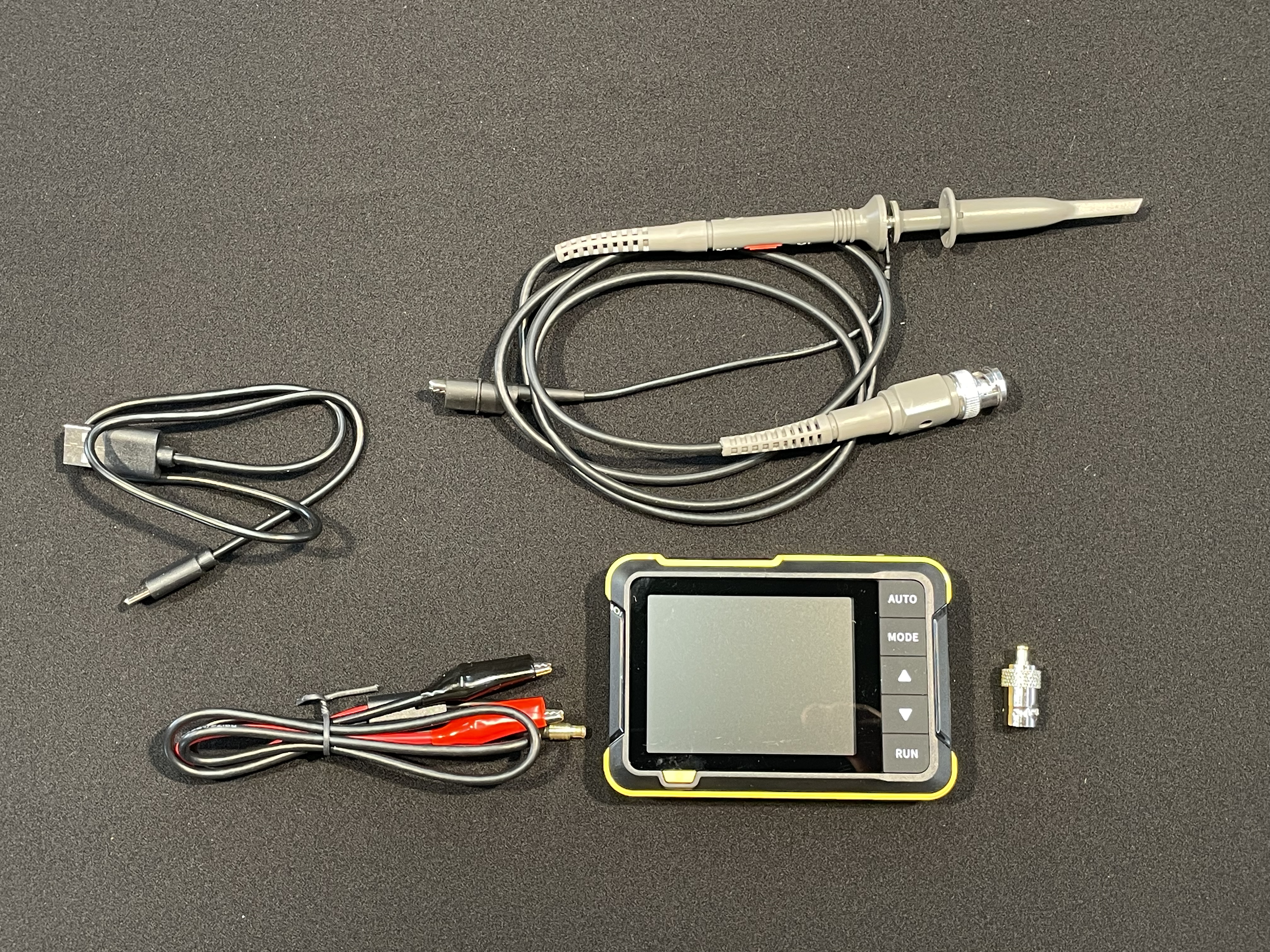
A flat-lay photograph of electronic testing and measurement equipment displayed on a gray surface. The kit includes an oscilloscope with a yellow-green rugged case and digital display, various probe cables with connectors, a soldering iron with stand, and test leads with alligator clips. This appears to be a typical electronics troubleshooting or repair kit used for measuring electrical signals and testing circuits.
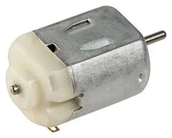
A small electric motor with a gray metal cylindrical housing and a white plastic mounting bracket or base. The motor has a protruding shaft and appears to be a basic DC motor commonly used in educational robotics and electronics projects.

A circuit board showing electronic components including a ULN2003AN motor driver IC chip, four resistors labeled R5-R8, a white connector block with positions A-B-C-D, and mounting holes. This appears to be a motor control circuit board commonly used in educational robotics projects.